 Jinmai Plastic

To estimate a corrugated plastic divider cell size, start with the usable inside dimensions of the container. Subtract the space needed for the grid-to-box fit and internal divider walls, then divide by the number of cells. Subtract any cell-facing lining and compare the remaining opening with the maximum part size plus the required handling clearance.
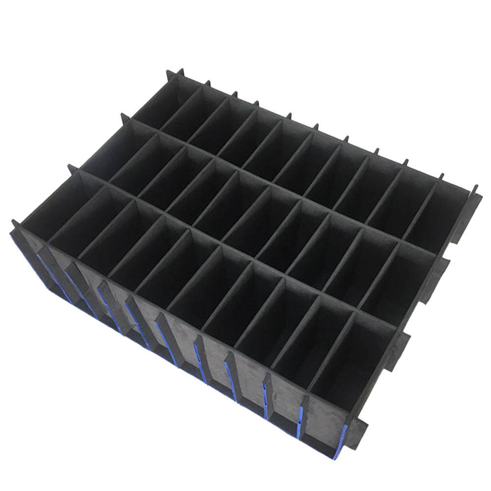
This calculator helps buyers prepare a layout for custom PP hollow-sheet divider inserts, also called knife-card dividers. It answers a specific purchasing question: will the proposed number of parts fit in the available space once the divider material is included?
Use the result to discuss a drawing and sample with the supplier. It is a geometry estimate; it does not establish payload, stacking strength, transport protection or service life.
Calculate clear cell size
Enter dimensions in millimeters. Inch equivalents are shown for reference; 1 inch equals 25.4 mm. Keep one controlling unit on the manufacturing drawing.
Jinmai / divider sizing
Divider cell-size calculator
For an evenly divided rectangular grid with equal-thickness dividers and fixed part orientation. Prefilled values are a hypothetical teaching example, not standard product specifications.
Usable interior mm
Divider + lining mm
Part requirement mm
Arithmetic fit
- Finished cell L
- 96 mm
- Finished cell W
- 96 mm
- Required L × W
- 94 × 92 mm
- Clearance margin L × W
- 2 × 4 mm
No perimeter frame is included. UL/UW are already net of frame or protrusions.
Scope: equal rectangular cells, same-thickness dividers, fixed part orientation, equal wall-face lining, and no perimeter frame. No deformation allowance is included. Inch reference: 1 in = 25.4 mm. Results are displayed to two decimal places; the fit comparison uses unrounded values.
JavaScript is needed to update this calculator. Use the formula and worked example below for a manual calculation; displayed values are the initial example only.
The model assumes a rectangular grid with equal cells, uniform divider thickness, a fixed part orientation and no separate perimeter frame. Each internal divider is counted once. The entered lining thickness applies to both opposing faces of every cell, including the boundary faces. This assumes the boundary faces are also lined in the actual design. If a box wall is unlined or only selected surfaces are lined, calculate the affected edge cells separately rather than applying a uniform deduction.
Use the container’s clear rectangular space after accounting for inward-facing hardware, overlaps, handles, frames and other obstructions. For tapered or irregular containers, a single overall length and width may not describe the available space at every height.
Three dimensions that must stay separate
| Dimension | What it describes | What to send the supplier |
|---|---|---|
| Usable container size | The space available for the complete insert at its installed position | Inside length, width and height, measurement condition and any intrusions |
| Clear cell size | The opening between the finished product-facing surfaces | Required minimum opening after lining, plus the drawing reference |
| Part envelope | The largest space occupied by the part in its loading orientation | Maximum dimensions including projecting features, bags or individual wraps |
A box described as “400 × 300 mm” could refer to outside dimensions, nominal inside dimensions or usable space. Those descriptions are not interchangeable. An RFQ should identify which one applies. Kiva Container’s divider-system guidance likewise asks buyers for the internal dimensions of an existing container when developing a divider set.
The broader corrugated plastic boxes with dividers guide covers assembly styles and application choices. This worksheet focuses on the space occupied by the grid and its contents.
The cell-size formula
Calculate each horizontal direction separately:
Clear cell opening = [usable span − 2 × edge allowance − (cell count − 1) × divider thickness] ÷ cell count − 2 × lining thickness
In this formula:
- Usable span is the clear container dimension along the direction being checked.
- Edge allowance is the space reserved at each end between the insert arrangement and the container. It is separate from clearance around an individual part.
- Cell count is the number of equal cells along that direction.
- Divider thickness is the thickness of an unlined internal wall. There are one fewer internal walls than cells along each axis in this simple grid.
- Lining thickness is the allowance for the facing on one side of a cell. Enter zero for an unlined model. For compressible facing, agree on the thickness and measurement condition used for fit review.
Then compare the result with:
Required cell opening = maximum part dimension + total handling clearance along that direction
“Total handling clearance” means both sides combined. For example, a hypothetical 2 mm total allowance means 1 mm on each side if the part is centered. It does not mean 2 mm on each side, and it is not a recommended clearance for every project.
The calculator reports the difference between available and required opening. A positive number is spare geometric space within these assumptions. It is not an approved manufacturing tolerance.
Worked example: a 12-cell divider layout
All dimensions in this example are hypothetical teaching inputs, not Jinmai stock sizes or guaranteed manufacturing capabilities.
Assume the following proposed layout:
| Input | Example value |
|---|---|
| Usable container length × width | 400 × 300 mm |
| Columns along the length × rows along the width | 4 × 3 |
| Unlined divider thickness | 4 mm |
| Edge allowance at each end of both axes | 2 mm |
| Maximum part length × width | 92 × 90 mm |
| Total handling clearance along each axis | 2 mm |
The calculated unlined openings are:
- Length: [400 − 4 − (3 × 4)] ÷ 4 = 96 mm.
- Width: [300 − 4 − (2 × 4)] ÷ 3 = 96 mm.
- Required opening: 94 × 92 mm, after adding the example handling allowances to the maximum part dimensions.
The unlined model therefore has 2 mm of extra opening along the length and 4 mm along the width, beyond the requested part-plus-clearance envelope.
Now consider 2 mm of lining on each of the two opposing cell surfaces. The finished opening becomes 92 × 92 mm. That falls 2 mm short of the required length, even though the bare divider layout appeared to fit. The design needs review: possible changes include the cell count, container size, facing arrangement or a different protection concept.
Do not reduce the handling allowance simply to make the calculation turn green. Confirm how operators or equipment will actually load and remove the parts.
Choose clearance from the loading process
There is no single clearance value to apply to every knife-card divider. Specify the movement and contact conditions the cell must accommodate.
| Question | Consequence for the layout |
|---|---|
| Can a protrusion, connector or flange be wider than the main body? | Include it in the maximum envelope or define an approved cutout and loading path. |
| Are parts bagged or individually wrapped? | Include the packaging in the loaded envelope. |
| Must an operator reach into the cell with gloves? | Check hand access, divider height and any finger notches on the sample. |
| Is a surface cosmetic or easily marked? | Identify permitted contact areas and review lining or another support arrangement. |
| Does a gripper need clearance during insertion? | Check the complete insertion and withdrawal path, not just the final resting position. |
| Can smaller parts move excessively? | Review the full part-size range and the agreed retention or protection requirements. |
More free space can make loading easier while allowing greater movement. A close fit can reduce movement while making loading difficult. Resolve that tradeoff with representative parts and an agreed trial rather than a universal gap rule.
What the calculator does not include
Slot width is a separate assembly requirement. The clear opening calculation does not specify how tightly two slotted strips engage. Slot geometry, actual sheet thickness, flute direction, cutting condition and assembly method belong on the supplier’s drawing. A slot that is too tight can distort the grid; a loose engagement needs review against the required stability.
Height needs its own check. Confirm divider seating, the support under the part, any layer pads, the lid and removal access. Adding cells in plan view does not establish that a tall part is supported or that a loaded lid will close.
Manufacturing variation matters. When appropriate data are available, review the smallest usable container space, the largest divider and facing thicknesses, and the largest loaded part envelope. Record what is measured and under which conditions. For a controlled production drawing, use the box drawing and tolerance guide.
Fit does not establish strength. Coroplast’s packaging material guidance notes that performance figures can vary with resin batch and finished-container production quality. Its material information is not a load rating for a Jinmai divider. Agree on package-level verification separately when handling, stacking or transport loads matter.
Turn the calculation into a sample review
Ask the supplier to identify the drawing revision, proposed material and sample configuration. Then check the following before approving production:
- Assembled opening: measure the finished cells after the grid and any facings are installed. Check representative edge and center cells.
- Container fit: install the insert in the intended container and inspect for bowing, trapped edges, interference or unwanted movement.
- Loading and removal: use representative parts, wraps, gloves and handling equipment. Include the relevant part-size variation.
- Contact condition: inspect the surfaces where the product meets the divider, edges, slot junctions or lining.
- Height and closure: check supports, layer pads, lid clearance and access at the intended packed quantity.
- Handling acceptance: perform the agreed handling or transport evaluation and record the results against the project’s acceptance criteria.
A successful fit demonstration supports the tested configuration. Changing the sheet, lining, cell count, part orientation or container can require another review. Use the separate receiving inspection checklist when delivered units need checking against that approved reference.
Download the divider sizing worksheet
Download the divider sizing and RFQ worksheet (CSV)
The worksheet separates your measurements from supplier proposals and approval evidence. Fill in the part envelope, usable container space, row and column count, clear opening, material and facing assumptions, loading method and sample requirements. Leave unconfirmed dimensions marked for review.
For a standalone grid or an insert supplied with a matching box, see Jinmai’s custom corrugated plastic divider inserts and the Divider / Insert (Knife Card) category.
If the outer container must fold for the return trip, also explain whether the divider stays assembled, is removed or is packed separately. Review the insert together with the foldable corrugated plastic box; a folding box does not establish that its installed divider folds with it.
Frequently asked questions
How many cells fit in my corrugated plastic box?
Start with a proposed row and column count, then calculate the finished clear openings after divider walls and facings. Compare both directions with the maximum loaded part envelope plus handling clearance. Increasing the number of cells reduces the space available for each part; the practical count also depends on height, access and sample results.
Should I use the box’s inside or outside dimensions?
Use the usable inside dimensions at the installed insert position. Identify any frame, hardware or tapered walls that reduce that space. Outside dimensions remain relevant to pallet, rack and shipping requirements, but they do not tell you the clear space available for the divider.
Is divider cell size the same as slot pitch?
No. Clear cell size is the opening between product-facing surfaces. Slot pitch locates repeated features on a strip. Divider thickness and any facing affect their relationship. Ask the supplier to dimension both the assembled opening and the features needed to produce it.
Can the calculator approve an ESD or delicate-surface packaging design?
It only checks the stated geometry. Electrical properties, surface contact, cushioning and transport performance require their own specifications and verification. The material grade or protection level cannot be inferred from the grid shape or color.
Send the measurements with your RFQ
Share a part drawing or sample details, its maximum loaded dimensions, the usable container size, required quantity per box and the completed worksheet. Identify the contact surfaces and loading process, then ask Jinmai to review the cell layout, material and sample plan together.
Request a custom divider layout review
Method note: The calculator uses the simplified geometry stated above. Its examples are illustrative, not test results. Source references support the need for internal container dimensions and project-specific material evaluation; they do not certify this calculation or a finished Jinmai product.